Issue 8 - February 2015
Update 8 provides clarification and further information on technical issues relating to the residential guidance (Repairing and rebuilding houses affected by the Canterbury earthquakes). These issues result from new information or feedback received on the guidance since its publication in December 2012.
BRANZ Test Report SC1221/1, Capillary test on tailings with liquefaction sand filling the voids, Report to MBIE, 1 December 2014
54. What is the requirement for embedment depth for the underslab of a Type 2A-150, 2A-300 and 2B surface structure foundations? For example can we embed it 100mm, and have 50mm or 200mm above ground depending on the underslab depth?
(Guidance document reference - Part C, section 15.4.4 and Q&As 45 & 46)
The underslab for Type 2A foundations shown in Figures 15.18 and 15.19 has been buried for aesthetic reasons and so that gardens could be planted adjacent to the house.
If it is preferred to raise the level of the underslab for either 2A or 2B surface structure foundations so that the underslab is only embedded 100mm into the ground and have it partially above ground, it would be advisable to use only one layer of DPM in order to improve the friction resistance to lateral sliding between slab and ground. The sub-base needs to be well prepared. Care should also be taken against the possibility of localised undermining of the slab.
55. Are the DELETION references in the margins in the Residential Guidance referring to text that has been removed?
For the avoidance of doubt; DELETION in the margin means that a deletion has occurred from the previous version and what you see in the text still applies, i.e. the text next to the deletion note remains part of the current guidance.
56. The partial replacement of slabs or the raising of slabs by injection through the slab can damage the polythene Damp Proof Membrane (DPM) under the slab. What is required to reinstate the vapour barrier to ensure appropriate moisture control?
(Guidance document reference - Part A, Appendix A 4)
The impact of gaps in or damage to the DPM is cumulative. Occasional spot gaps in the vapour barrier, whether at laps or from individual holes dispersed across the floor that are no more than half the slab thickness in diameter, are not likely to significantly impair barrier performance. However where there is a line of damage then repair is required.
Check that the DPM remains an effective vapour barrier
It is important to remember that the function of the DPM is to provide resistance to vapour movement. The DPM has never been intended to be a tanking material. Consequently, this answer only applies to situations where water pressure cannot build up on the underside of the membrane (i.e. the water table is lower than the membrane). This answer requires that at least one of the following conditions are met:
- The water table is at least 500mm below the DPM ; or
- There is well graded and compacted granular material under the slab, or,
- Where rounded, poorly graded river run material (tailings) has been used as sub-base, fine sand particles have not filled the voids (as a result of liquefaction) and formed a migration path for ground moisture to the underside of the DPM.
Satisfying any of these conditions will ensure that capillary rise is controlled (refer Reference 1 below).
Ideally water table information could be obtained from long term monitoring of an appropriate standpipe. It is rare however for this information to be available for a specific site. Therefore, it is recommended that the designer compare the ground level elevation for the site in question with the 85 percentile groundwater table information held on the Canterbury Geotechnical Database. This will provide guidance on whether the groundwater level is within 500mm of the vapour barrier (refer Reference 2 below).
Records of liquefaction observations will assist in determining the level of investigation required to establish the second condition. If liquefaction was present then testing adjacent to the slab is recommended.
If there is a reasonable likelihood that the water table may be within 500mm of the vapour barrier and that liquefaction material is present, then an intrusive investigation through the slab is likely to be required to establish that the tailings are still clean. A hole of approximately 300mm square or diameter in the slab should be sufficient for this purpose.
Where the water table is less than 500mm below the level of the DPM under the slab and fine sand particles have filled the voids in the tailings, specific advice should be obtained regarding suitable repair strategies for the particular site conditions.
Injection points
For holes drilled in the slab for relevelling the slab by injection, the reinstatement requirements are different depending on the diameter and spacing of the holes used.
Where holes are up to 50mm in diameter and spaced more than 1.2m apart, the drilled holes will comprise typically less than 0.1% of the surface area of the DPM and, for the reasons noted above, are not likely to significantly impair barrier performance. While cement grout is less likely to provide a (plug) repair to the DPM at these holes, it is expected that the likelihood of vapour leakage through the holes is negligible.
Where a closed cell resin product is used to lift a slab, the resin can be expected to provide an adequate repair to the DPM once the injection is complete.
For holes larger than 50mm in diameter, the holes in the DPM must be repaired regardless of the spacing. There are specialist concrete additive products available on the market that will provide sufficient resistance to water vapour to effect an adequate repair to the DPM.
DPM evaluation beneath slab cracks
Field investigations to date have indicated that the DPM is typically undamaged beneath slab cracks up to 30mm wide (refer Reference 3 below).
When cracks are greater than 30mm, it should be possible to visually inspect the DPM for damage. If there is evidence of moisture which gives rise to concern about DPM failure beneath slab cracks up to 30mm wide, or beyond slab crack locations, there are moisture detection devices that can be used to carry out non-invasive and non-destructive investigations. Note that Table A4.1 of the MBIE Residential Guidance suggests slab break-out and partial replacement for cracks greater than 20mm.
Also refer generally to Appendix A4 of the Residential Guidance.
Partial Slab replacement
At the junctions of replacement slab sections the new piece of polythene DPM must overlap the existing by a minimum of 150mm and be taped in accordance with 7.5.6.1 of NZS3604. Care must be taken during the cutting out process to avoid damage to the DPM beneath a slab. The following process is suggested for taping the new DPM to an undamaged in-place DPM.
- Mark out the junction on the slab between the part to be retained and the part to be replaced.
- Cut out and remove the slab 200mm inside the replacement line.
- Check slab depth and reinforcement location and cut along junction line at a depth of 10-20mm less than measured slab depth making sure all reinforcing is cut.
- Excavate granular base or tailings from under cut section to remove support. Drop DPM out of the way.
- Inspect exposed base/tailings and ground, and removed base/tailings for evidence of high water table and/or liquefaction material. If the two conditions stated above are satisfied, then proceed; if not, seek specific advice.
- Manually and carefully break out slab section, cutting into smaller sections as required, and fold back DPM for access to granular base. This will require careful cutting of the existing DPM diagonally, almost into the corners of the broken out section.
- Provide granular base to 7.5.3 of NZS3604 and prepare surface suitable for polythene DPM to 7.5.6.2 of NZS3604.
- Lay new DPM and fold down existing DPM. Trim edges to be tidy and straight, suitable for taping, and ensure lap remains a minimum of 150mm. Tape lap to 7.5.6 of NZS3604.
- Pour new concrete section to 7.5.8 of NZS3604. reinforcing steel is required in the new slab concrete and must be adequately tied to the retained slab on both sides.
At internal corners of slab cut-outs it may be difficult to achieve no damage to the retained DPM or complete laps between new and retained DPM. For the reasons noted above, small holes in the retained DPM or small gaps in the new lap are not likely to be of any consequence.
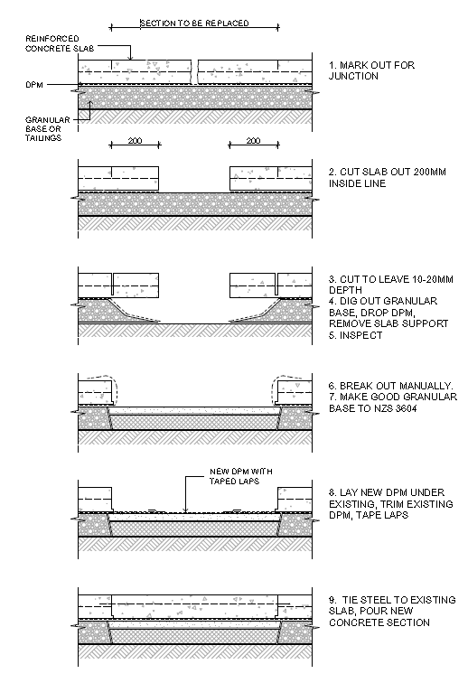
Figure 1: Steps in the partial removal and replacement of a slab with DPM reinstatement guidance.
References
- BRANZ Test Report SC1221/1, Capillary test on tailings with liquefaction sand filling the voids, Report to the Ministry of Business Innovation and Employment, 1 December 2014.
- van Ballegooy, S.; Cox, S. C.; Thurlow, C.; Rutter, H. K.; Reynolds, T.; Harrington, G.; Fraser, J.; Smith, T. (2014) Median water table elevation in Christchurch and surrounding area after the 4 September 2010 Darfield Earthquake: Version 2, GNS Science Report 2014/18, April 2014. ISBN 978-1-927278-41-3. 79 p and 8 Appendices.
- G J Beattie, Report to the Residential Engineering Advisory Group ‘Condition of polythene DPM under cracks in concrete floor slabs’, 8 August 2012).
57. What are the skill requirements for people taking measurements of levels and wall verticality as part of the information gathering toward determining a repair strategy?
(Guidance document reference- Part A, Section 2.3)
Due to the widespread uses to which levelling data may be put, and the many techniques available, no one specific measurement method can be recommended. In cases of doubt about the status of the floor levels, only a competent person or someone operating under the direction of a competent person should make decisions on measurement methods and equipment.
Residential new building level and verticality is often set out by the builder who is familiar with the building standard tolerances and equipment needed to achieve the required result. Where the results of the survey do not clearly indicate to the engineer how the building has performed during the earthquake sequence and that a more accurate survey may help in the assessment, the engineer should consider engaging a survey specialists such as a Registered Professional Surveyor (RPSurvs) or Licensed Cadastral Surveyor (LCSs). For more information the following reference is relevant:
References
- Report from the NZIS Working Party – Review of Survey Practices in Relation to the Canterbury Rebuild June 2014.
58. What was the outcome of the review of the guidance on Type 2 foundation plywood skirts referred to in Q&A 44?
(Guidance document reference - Part C, Section 15.4.4)
Figure 15.21, Detail of plywood stiffening to Type 2 surface structures, has been superseded. In Q&A 44 the need for the plywood skirts for Type 2A foundations was stated to be under review. In the Part E guidance on MUBs, page 22.2, the requirement for perimeter skirts was removed for Type 2A and Type 2B foundations under MUBs. This guidance now applies to all residential use of the Type 2 foundations provided they are within the height limits set in Table 20.4.
Repairing and rebuilding houses affected by the Canterbury earthquakes