Head flashings in E2/AS1
This guidance describes the critical measurements needed for weathertight performance of the joint between flashing and window flange.
The information was confirmed as current in November 2017. It originally appeared in Codewords 61.
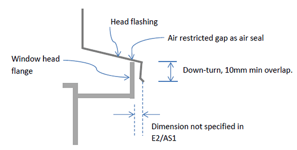
E2/AS1 outlines critical dimensions for head flashings, but does not give a dimension for the gap between the head flashing and the window head flange.
The image below demonstrates that some details show a ‘touch’ fit, and others an unspecified gap.
Installations on-site have produced varying gaps. Therefore questions are asked whether gaps are acceptable, or whether a tight contact is needed between the front edge of the head flashing and the window flange.
Head flashing details from E2/AS1
Few flashings are ‘folded to fit’ these days. Most head flashings for aluminium windows are extruded section, manufactured to a range of ‘standard’ widths. The standardised widths are to accommodate the range of offset dimensions of window flanges from the frame, influenced by underlay type, cavity battens (or direct fix), and cladding type.
Builders (and window suppliers) should use the ‘nearest fit’ size of an extruded head flashing to suit each job.
Overhang dimensions
If a head flashing is so tight that it is difficult to engage the window frame it will risk distorting the head flashing and damaging the window frame coatings. A gap for ‘fitting tolerance’ is required.
The following are some considerations for determining acceptable gaps of head flashing to flange.
- It is important to prevent water runoff occluding (blocking) the joint between the flashing and window facing. Air pressure differences through the joint could force this water up and over the window flange. Either a kick-out along the bottom edge of the flashing and/or an overhang of the flashing is necessary to deflect water off the joint.
- Most extruded head flashings are fabricated in 5–6 mm width increments. It is possible therefore to select a width that will result in an overhang gap not exceeding 6 mm. However, if kick-outs are not incorporated a minimum overhang of 3 mm is needed to avoid occlusion. Therefore gap (overhang) ranges of between 0–9 mm will be sufficient to accommodate all head flashing options.
- Head flashings in sheltered zones (within 45° of an overhang) might accommodate wider overhangs of the head flashing due to reduced risk of water entry. However, wider overhangs are prone to deformation or ‘flutter’ in higher winds. For this reason, the 0–9 mm limit should apply in all situations.
Air seals
When installing the head flashing, make sure it is in contact with the top edge of the window flange. This:
- ensures the maximum overlap dimension of the ‘down-turn’ part of the head flashing
- acts as an effective air seal to prevent air/water intrusion through the joint.
An effective air seal for lower wind zones can be achieved by close contact of the flashing onto the top edge of the flange. For higher wind zones, a sealant or compressed foam seal in the gap is more effective.
Note that E2/AS1 requires a sealant bead along this joint in Very High and Extra High wind zones (E2/AS1 Figure 71c).