Practice Advisory 20: Improving earthquake performance of secondary structural elements
Careful design and construction monitoring of secondary structural elements will ensure good earthquake performance, which can save lives and costs. This Practice Advisory advises how to improve the performance of secondary structural elements during earthquakes.
This information was confirmed as current in December 2016.
This Practice Advisory is issued as guidance information in accordance with section 175 of the Building Act 2004 and, if used, does not relieve any person of the obligation to consider any matter to which the information relates according to the circumstances of the particular case. This document is not a compliance document in terms of the Act and not a substitute for professional advice.
Purpose
To alert building professionals to the need for careful design and construction monitoring of secondary structural elements to prevent poor performance in earthquakes.
Secondary structural elements
Secondary structural elements are those elements of the building that are not part of either the primary lateral or primary gravity structural systems but nevertheless are required to transfer inertial and vertical loads. Examples of secondary structural elements include precast panels, curtain wall framing systems, heavy internal partitions, stairs, significant building services and large building ornaments.
This defintion aligns with definitions in The Seismic assessment of existing buildings which categorises elements into primary, secondary, or non-structural. (refer to Practice Advisory 19).
Make secondary structural element design and construction monitoring the responsibility of an engineer with suitable competency and qualifications in structural engineering, such as a Chartered Professional Engineer (CPEng), who is appropriately experienced in the application of earthquake actions.
Issues of concern
The damaging earthquakes in Canterbury (2010/2011) and Wellington (2013) have highlighted many cases of poor performance of secondary structural elements, particularly in multi-storey buildings.
The collapse of stairs in several buildings were of particular concern. Refer to Practice Advisory 13 for more guidance on specific checks that should be performed on egress stairs.
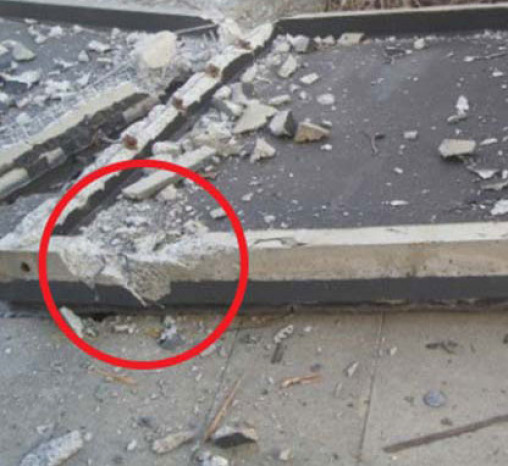
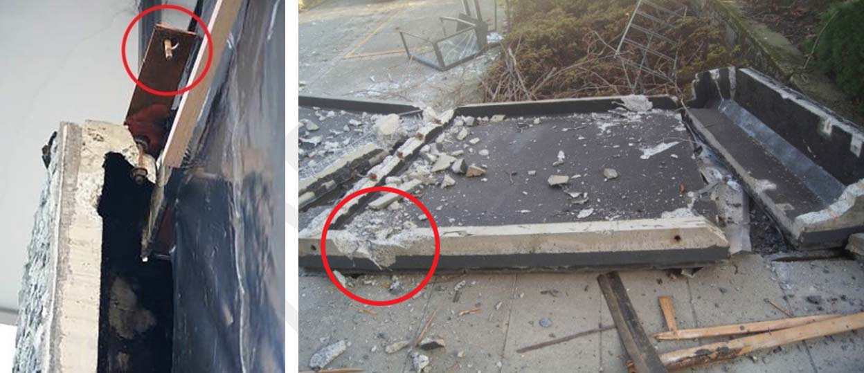
In Canterbury, secondary elements, such as precast concrete panels suffered impact damage through insufficient clearances and significant damage occurred to the connections. Several low rise mall and supermarket type buildings lost precast cladding panels which fell to the street below. See Figure 1.
The failure of secondary elements during earthquakes can be a life-safety hazard and their failure can result in significant disruption and economic loss. Attention to structural engineering design is required to ensure that these elements meet the provisions of the Building Code.
Building Code requirements and supporting documents
The Building Code Clause B1 Structure requires all building elements to have a low probability of failure when exposed to the physical conditions likely to be experienced within their lifetime.
A building element is any structural or non-structural component, or assembly incorporated into, or associated with the operation of a building. Secondary structural elements are therefore required to accommodate earthquake actions.
All secondary structural elements and their connections therefore need to be designed to resist the earthquake demand including differential movements of their attachment points. The specific design document for complying with the structural performance requirements of the New Zealand Building Code is Verification Method B1/VM1, which references NZS 1170.5 Earthquake actions for New Zealand. Section 8 of NZS 1170.5 contains a design procedure to determine the demand for secondary structural elements in accordance with the risk level, the properties of the part and the type of building.
For the design of specific elements and their connections to resist earthquake actions, Verification Method B1/VM1 references the following Standards:
- NZS 3101: 2006 Concrete Structures Standard
- NZS 3404: 2009 Steel Structures Standard
- AS/NZS 4600: 2005 Cold-formed Steel Structures
- NZS 3603: 1993 Timber Structures Standard
- NZS 4230: 2004 Design of reinforced concrete masonry structures.
Secondary structural elements and their connections, both individually and as a part of a system, must also meet the applicable durability requirements of Building Code Clause B2 according to location and use. In many cases, this will be a minimum of 50 years. Some parts of systems such as glazing and gaskets of curtain wall glazing systems will have a less onerous requirement.
Designing for earthquake actions
Each secondary structural element and its connections need to be carefully detailed for the earthquake actions they will be subjected to. These actions will include gravity load, earthquake inertial and interstorey displacements imposed by the primary lateral load resisting system. Alternatively the elements may be separated from these displacements.
The effects of other secondary or non-structural elements must also be considered. Where seismic joints are detailed, secondary structural elements should not span across these joints unless separation details are provided.
Secondary structural elements and their connections should have robust details and have clear and simple load paths, that are easily verified, from the element through the connections into the primary structure. Load paths should account for over-strength actions as appropriate and should accommodate actions associated with an earthquake larger than an ultimate limit state design event. Back up alternative load paths with ductile detailing can also provide a measure of resilience.
Non-load bearing walls
Non-load bearing walls will need to be designed to resist their own inertial forces and the differential movements of their attachment points. The member and the connections may be designed to respond elastically or in a ductile manner. A common detail in framed buildings is to design the wall to be fixed at the base and restrained at the top against out-of-plane movement but to allow in-plane movement at the top and sides to accommodate interstorey displacements.
Columns
Columns that are part of the primary gravity load system that do not contribute to the primary lateral resistance system need to be designed and detailed to accommodate the design gravity load together with the interstorey displacement. These columns are normally required to be detailed to allow ductile behaviour.
Floors
Secondary structural elements such as precast floor units need to be designed to resist frictional forces* generated by movement of their supports. Bearing strips are often used to reduce this friction. Precast floor units need to have sufficient seating to accommodate:
- construction tolerances
- movement due to temperature changes
- creep
- shrinkage
- foundation/soil deformations
- elongation or rocking
- permanent inelastic deformations of the element between supports
- the potential reduction of the support due to spalling.
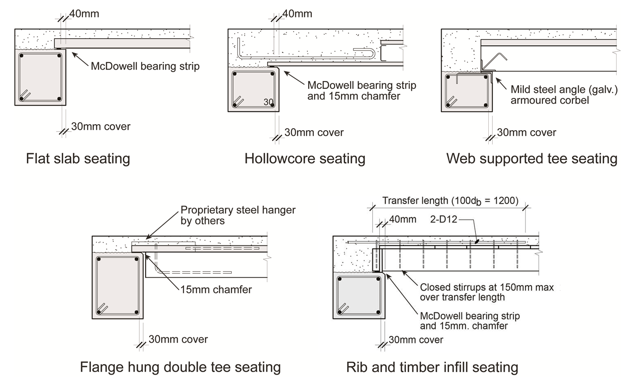
Figure 2 shows recommended precast floor seating details for various floor systems developed by the Structural Engineering Society (SESOC). See SESOC Interim Design Guidance (Reference 12) for more detail.
*Note: The friction values given in NZS 3101 for the details in Figure 2 are appropriate for seating on continuous low friction bearing strips. For secondary elements that span between floors/joints etc use friction values appropriate to the sliding surfaces.
Stairs
Secondary elements such as stairs that span between floors need adequate seating at the maximum possible inter-storey displacements between the relevant levels. Clearances and seatings for stairs should be capable of sustaining at least twice the Ultimate Limit State (ULS) inter-storey displacements as calculated in accordance with NZS 1170.5, after allowance for construction tolerances.
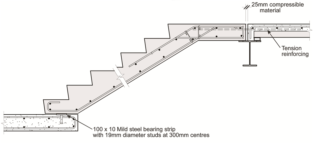
Stairs need to be designed for lateral as well as longitudinal earthquake actions. Therefore inertial earthquake actions need to be considered in both principal directions. It is recommended that stairs should be restrained at the top level. The lower level should be detailed to provide vertical support, with minimal lateral restraint, and accommodate twice the calculated ULS interstorey drifts in both principal directions. An example that will provide this degree of movement allowance is shown in Figure 3.
This will take into account tolerances and the anticipated variability and uncertainty of calculated building displacements including an allowance for earthquake shaking larger than the ULS event. Designers should allow for minimum and maximum coefficients of friction in the design of stair connections. Note that yielding of the tension reinforcing at the fixed (upper) stair level will add to the transverse movement at the sliding end of the stairs.
Gap and ledge details should be avoided because they are restrictive and prone to filling up with debris. If movement allowance is provided by a gap and ledge detail, the gap should be detailed to prevent inadvertent filling of the gap. One way to achieve this is to provide cover plates that allow movement but prevent debris filling the gap. In all cases the separation details between elements should be identified on the design drawings with notes to highlight the specific clearances that need to be confirmed as part of the construction monitoring process. Practice Advisory 13 contains more advice with regard to checking egress stairs in existing buildings.
Precast panels
Precast cladding panels must be designed for in-plane and out-of-plane actions. Care is required to ensure there is sufficient allowance for movement. Particular attention is required where panels meet at corners and may be subject to dual actions. This is illustrated in Figure 4. A level of resilience can be provided by designing the connections with adequate ductility in the event that clearances are exceeded. Where precast panels are supported at more than one level in buildings they need to be designed to sustain the actions resulting from the inter-storey deformations that will occur. See SESOC Interim Design Guidance (Reference 12) for further advice.
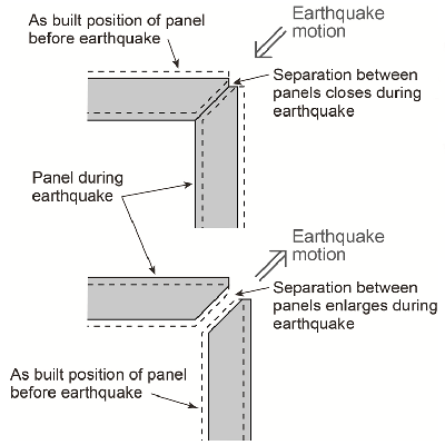 Figure 4: Panel separation requirement at building corners
Differential inter-storey drift
Another area where there is a need for careful detailing of secondary structural elements is where there are significant differences in inter-storey drift between adjacent floors. For example considerable difference in drift may occur in a building where fenestration requirements for a particular storey require a change in the primary structural system.
For engineers/designers
Ensure all secondary structural elements and their connections comply with the Building Code.
Include a section on secondary structural elements in the Design Features Report as well as providing relevant information on the specification and drawings. The report should contain relevant information for designers of secondary structural elements and their supports so they are aware of expected performance.
For BCAs
Check that the design documentation adequately covers secondary structural elements.
Buildings with low-damage systems
Take care with some low-damage building systems that may result in large displacements. These displacements will need to be accommodated by secondary elements. Systems that reduce earthquake actions such as base isolation of a building are an effective way of protecting secondary structural elements. However these displacements still need to be considered
Construction monitoring
On-site construction monitoring is crucial to verify that design details are built as intended. Particular attention should be applied to critical design information, such as fixing/anchorage details and seismic clearances, eg, clearances between non-load bearing panels and building columns.
For BCAs
Check that the design details have been built in accordance with the consented documents before issuing the Code Compliance Certificate.
Maintenance
Seismic gap details should be inspected periodically to ensure that the gaps have not been partially or fully filled during construction or as a result of poor maintenance. This is especially important with egress stairs because obstructing the seismic gap may restrict or prevent movement resulting in failure of the stairs and the loss of an escape route from the building.
References
- Standards New Zealand. NZS 1170.5:2004. Structural Design Actions Part 5: Earthquake Actions - New Zealand. Incorporating Amendment No.1 (September 2016).
- Standards New Zealand. NZS 3404. Parts 1 and 2:2009. Steel Structures Standard.
- Standards New Zealand. NZS3603:1993 Timber Structures Standard.
- Standards Australia/Standards New Zealand. AS/NZS 4600:2005. Cold-formed Steel Structures.
- Standards New Zealand. NZS 3101. Parts 1 and 2:2006. Concrete Structures Standard.
- Standards New Zealand. NZS 4320: 2004. Design of reinforced concrete masonry structures.
- Ministry of Business, Innovation and Employment (MBIE) (2011). Practice Advisory 13 – Egress Stairs: Earthquake checks needed for some.
- Ministry of Business, Innovation and Employment (MBIE) (2013). Guidance on the use of Certificates of Work, Producer Statements, and Design Features Reports by Chartered Professional Engineers under the new Restricted Building Work regime.
- Ministry of Business, Innovation and Employment (MBIE) (2014). New Zealand Building Code Handbook.
- Ministry of Business, Innovation and Employment (MBIE) (2014). Acceptable Solutions and Verification Methods for New Zealand Building Code Clause B1 Structure.
- Institution of Professional Engineers New Zealand (IPENZ) (2014). Practice Note 1 – Guidelines on Producer Statements [PDF 1.4 MB].
- Structural Engineering Society New Zealand (SESOC). Interim Design Guidance. Design of Conventional Structural Systems Following the Canterbury Earthquakes. Version 9, 26 March 2013.
- New Zealand Concrete Society (NZCS) – New Zealand Society for Earthquake Engineering (NZSEE) – Structural Engineering Society New Zealand Inc (SESOC) – New Zealand Timber Design Society (NZTDS). Building Performance in the 22 Feb Christchurch Earthquake. Seminar Notes (2011) and University of Canterbury. Stephano Pampanin and Weng Yuen Kam. National Hazard Research platform: Resilient Buildings and Infrastructure.
Further information resources
- New Zealand Society for Earthquake Engineering Inc. (NZSEE et al) (2016). Seismic assessment of existing buildings.
- MacRae, G.A., Pampanin, S., Dhakal, R., Palermo, A., Baird, A., & Tasligedik, S. (2012). Review of Design and Installation Practices for Non-structural Components. National Research Hazard platform.