Practice Advisory 12: Unstiffened eccentric cleat connections in compression
If you're a structural design engineer, you need to be aware of problems when using unstiffened eccentric cleats to connect compression members such as braces and frame members to supporting members. This guidance also alerts you to a flawed design method.
This information was confirmed as current in December 2016.
This Practice Advisory is issued as guidance information in accordance with section 175 of the Building Act 2004 and, if used, does not relieve any person of the obligation to consider any matter to which the information relates according to the circumstances of the particular case. This document is not a compliance document in terms of the Act and not a substitute for professional advice.
Flawed method
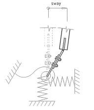
There are published methods which erroneously assume restraint is provided and that the connection will behave in the sway prevented manner shown by Figure 4. One such method is the design procedure in Section 9.3 of the AISC (now ASI) handbook ‘Design of Structural Steel Hollow Section Connections’ 1996 (The ASI Bluebook). This method has been recognised by the industry as being fundamentally flawed and should not be used. The method assumed the supported member was laterally restrained which is demonstrably incorrect and rare in practice. This flawed assumption led to unrealistically high (theoretical) connection capacities.
 |
 |
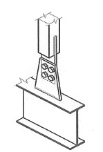
| Figure 3. Portal knee brace | Figure 4: Flawed assumption (side sway prevented)
Sway is prevented and three or four plastic hinges develop. This condition very rarely occurs in practice because the brace or frame members are normally not restrained and therefore the connection is free to translate laterally, i.e. sway. |
Design method
In each application the load transfer mechanism between the connection plates must be carefully considered taking into account the provision or lack of lateral restraint provided and using the design rules for combined bending and compression in the Steel Design Standard NZS 3404. HERA has developed a design procedure for unstiffened eccentric cleat connections without lateral restraint and for partially stiffened eccentric cleat connections without lateral restraint. The procedures, together with examples, are contained within HERA Report R4-142.
Recommended limited use of the unstiffened connection with no lateral restraint
The unstiffened eccentric cleat connection should not be used if the connection is a critical part of the load path and there is no redundancy, where the dominant design load is gravity load or where the magnitude of the load is uncertain. Where in doubt, use a concentric connection or a stiffened single eccentric cleat connection.
As overstrength load conditions in an unstiffened connection will result in a brittle failure, the unstiffened eccentric cleat connection is unreliable for use a connection with any Category 1, 2 or 3 primary members carrying seismic loads and designers should be careful about using this detail with Category 4 members (refer to NZS 3404: 1997).
Combined tension and compression connections
Eccentric cleat connections carrying both tension and compression members framing into the same joint (such as angled truss web members framing into a connection plate from a truss chord) can also be subject to sway. In this case the tension force across part of the plate will provide limited stability against sway buckling to the part of the plate in compression. HERA report R4-142 contains geometric limits on this application.
For cases outside these limits a finite element analysis can be used to determine when stiffening of the compression part of the connection plate is necessary.
Other design considerations
Note that this practice advisory only addresses the design of the cleats, i.e. the behaviour of the connection plates between the supporting and supported members. Design engineers must carefully consider the load transfer mechanism between the connection plate and the supporting or supported member taking account of proper load spreading principles.
Existing installations
Design engineers who are aware of eccentric cleat connections which may be deficient because they have been designed using flawed methods or assumptions and are a critical part of the structural system carrying gravity loading with no redundancy, should as soon as possible advise the building owner accordingly and recommend the connections be assessed for structural integrity.
Design concern
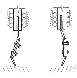
The connection of concern is where two unstiffened plates are bolted together side by side, similar to Figure 1 below. With hollow sections the supported member connection plate often consists of a flattened end of the hollow section, a welded tee end or an unstiffened plate welded into the slotted end of the member. The supporting member connection plate is also unstiffened.
The eccentricity moment, induced by the axial load because of the plate eccentricity, is shared between the two plates and unless there is moment restraint to prevent side sway each of these plates will deflect laterally about the weak axis as it is loaded in compression. A plastic hinge can then develop in each plate leading to a sway failure at a much lower load than the section compression capacity of the weaker plate (see Figure 2 below). Construction out-of-tolerances can further reduce this capacity. Upon formation of the plastic hinges, further lateral displacement of the supported member occurs and connection load capacity rapidly drops off. Note that care is also needed where one plate is stiffened and the other unstiffened.
|
|
 |
|
Figure 1. Example of unstiffened eccentric cleat connection |
Figure 2. Sway occurs |
|
Don’t |
|
Don’t use the design procedure in Section 9.3 of the AISC publication ‘Design of Structural Steel Hollow Section Connections 1996’ (The ASI Handbook). This design procedure has been recognised by the industry as unconservative and fundamentally flawed. |
|
Don’t use the unstiffened eccentric cleat connection where the compression load cannot be reliably determined. |
|
Don’t use the unstiffened eccentric cleat connection where the connection is a critical part of the structural system carrying gravity loading alone and there is no redundancy. |
|
Don’t use the unstiffened eccentric cleat connection with any Category 1, 2 or 3 primary members carrying seismic load. |
|
Don’t use the unstiffened eccentric cleat connection where it is a critical part of the lateral load resisting system and there is insufficient redundancy. |
|
Do |
|
Do use a concentric connection as the first design option. |
|
Do use a stiffened eccentric cleat connection where an eccentric cleat connection is required |
|
Do carefully consider the load transfer mechanism between the connection plates and the supporting or supported compression members. |
|
Do use the HERA design method in HERA Report R4-142 for the design or assessment of an unstiffened or partially stiffened eccentric cleat connection. |
Figure 2 shows the common design case where restraint is not provided to the connection. Sway occurs resulting in two plastic hinges developing and the load carrying capacity reduces rapidly. If the supporting member is not rotationally stiff the compression capacity will be further reduced. The sway mode of behaviour has been shown to occur experimentally and in numerical modelling.
The connections that cause the most immediate concern are those that are a critical part of the structural system carrying gravity loading with insufficient redundancy or where connection failure would significantly reduce the moment or axial load capacity of the structural system. A relevant example is a portal knee brace connection which allows the knee to develop moment (see Figure 3 below).
References
- HERA Report R4 -142: 2007
- NZS 3404: 1997 Steel Structures Standard including Amendment 1 and 2.
- Design of structural steel hollow section connections, Volume 1: Design Models. AISC: 1996.